Insteon Glossary of Terms
Controller
The Insteon transmitter
Responder
The Insteon reciever
Blinking
LED turning on and off repeatedly
Dual-Band
An Insteon device that can send and receive both Insteon powerline signals and Insteon radio frequency signals
Ramp Rate / Fade Speed
The speed at which the load fades on or off
On-Level
The preset brightness level a device will return to when turned on
Link
A one way association between a controller and responder
Linking
A method for associating Insteon controller buttons with groups of Insteon responders such that the responders instantly return to a memorized state when the button is pushed. Links can be made manually with the set button or using software.
Unlinking
The process by which an Insteon device can remove stored links. Just as with linking, unlinking is a one-way process and should be performed in both directions for devices that are both controllers and responders of each other, as in a 3-way switch scenario.
Multi-Linking / Multi-Unlinking
A special mode that allows more than one link to be either created or removed simultaneously, without laborious set button presses. When in linking or unlinking mode, an Insteon device will continue to link to other devices until the set button is tapped or four minutes have elapsed, whichever occurs first.
Factory Reset
A process that erases all stored links and reconfigures the device to factory defaults.
Load
The device that you are controlling (e.g. a light bulb, ceiling fan, etc.)
On/Off
A device that can control its connected load to turn on and off but cannot dim. Usually a relay-based device.
Retry
A 2nd (or subsequent) attempt by a controller to send an Insteon signal, usually after an acknowledge is not received from the responder in the expected time-slot.
Scene
Multiple devices respond to memorized states. For example, a dinner time scene turns on the dining table light, dims the kitchen lights to 10%, backyard lights turn off and the thermostat adjusts to 72º.
Set Button
A button on an Insteon device that is used for setting or changing its properties
Simulcast
A method for increasing the reliability of message delivery in a network. When a node in a network sends a message, every other node that hears the message retransmits it at precisely the same time based on a global clock, provided that the message has not already been retransmitted some maximum number of times. Message propagation is more robust because each node adds its energy to the signal, much like voices in a choir. Simulcasting is much simpler than message routing because there are no routing tables to maintain and nodes can join the network without any installation procedure.
Factory Resetting Insteon Devices
Download the Insteon App
5 Reasons Insteon is Better than Wi-Fi for Your Smart Home

Insteon and AFCI (Arc-fault circuit interrupter) Circuit Breakers
Years ago, first generation AFCI breakers were manufactured with poor tolerances which caused false triggers from a variety of common appliances, including Insteon powerline signals. Later generations of AFCI breakers are better engineered for real-world electronics and do well at avoiding being falsely triggered. Today there are no issues with using AFCI breakers and our Insteon devices. However, if the installer fails to follow standard wiring rules associated with AFCI circuits, you may experience issues.
Follow these important rules when wiring devices on AFCI circuits:
- Any branch circuits that feed receptacles before switches should be pigtailed connections at the receptacle. This is where you wire the incoming wire and the wire from the panel side and the wire going down stream together with a third wire “the pigtail” that goes to the outlet. DO NOT USE THE OUTLET AS A SPLICE TO CONNECT THE INCOMING AND OUTGOING WIRES BY STABBING THEM INTO THE BACK OF THE OUTLET
- With AFCI breakers it is imperative that wall switches are connected to the same neutral that goes with that circuit. If switch box has two neutrals, only connect the switches neutral wire to the neutral from the circuit the switch is connected to. If an AFCI breaker wont reset after installing an Insteon switch it is because the wrong neutral was used. This can be a result of the electrician crossing neutrals in another box and not the fault of the wiring at the switch box itself.
- Loose or poor splices can cause a situation where an Insteon switch can trip an AFCI breaker. This is not the fault of the switch but the loose connection somewhere in the circuit.
If you are using AFCI breakers and experience false triggers with your Insteon system, please contact us at support@insteon.com and be sure to include the make and model of your AFCI breakers.
Google Assistant and Supported Insteon Thermostats
The Google Assistant supports control of several different Insteon Thermostats; you can increase or decrease the temperature and change modes just by asking the Google Assistant. Use the information in this article to identify if you have a compatible Insteon Thermostat. Note that an Insteon Hub (2245-222) is required to enable voice control from the Google Assistant.
Supported Insteon Thermostats
These Insteon Thermostats are compatible with Amazon Alexa and allow full voice control functionality of setting temperature and changing modes.
Insteon Wired Thermostat
- Model 2441TH (Revision 1.1 or later)

Unsupported Insteon Thermostats
These Insteon Thermostats are not explicitly incompatible with the Google Assistant but are not guaranteed to function as expected.
Insteon Thermostat for Heat Pumps
- Model 2732-242 (Any Revision)

Incompatible Insteon Thermostats
These Insteon Thermostats are incompatible with the Google Assistant and cannot be controlled.
Insteon Wired Thermostat
- Model 2441TH (Revision 1.0)

Insteon Wireless Thermostat
- Model 2441ZTH
- Model 2441ZTHR
- Model 2732-433
- Model 2732-432

Insteon Venstar Thermostat Adapter
- Model 2441V
- Model 2441VR

Insteon Venstar Integrated Thermostat
- Model 2491T1E
- Model 2491T1ER
- Model 2491T7E
- Model 2491T7ER

X10 Programming for Insteon Devices
Some (mostly older) Insteon devices are X10 ready, meaning that they can be programmed to respond to or control other devices via X10 commands. The reason Insteon devices have supported X10 is to allow an upgrade path for those with extensive X10 systems that want something more reliable. Now with over 10 years in the market, new Insteon devices have had X10 functionality phased out. X10 is a slower technology and can be significantly impaired with noisy electrical environments. Whenever possible we recommend upgrading X10 hardware to Insteon for the best possible home control experience.
This article covers all the aspects of how to program older Insteon devices with X10 features such as primary address and scene address.
Important: Except for setting or removing the primary address, all steps below require that you have an X10 controller that only sends House and Unit code (no On/Off command). Before attempting these steps you will need X10 hardware or software that supports the ability to send these commands (example: Maxi Controller #PHC02 or #SC503).
Setting the X10 Primary Address
1. Put your Insteon device into linking mode (press and hold the Set button for about 3 seconds
2. Send the desired X10 Primary Address followed by the ON 3 times (e.g. A1-AON A1-AON A1-AON)
Your Insteon device will exit linking mode and its LED will stop blinking
Removing the X10 Primary Address
If you are no longer going to control your Insteon device with an X10 address it is very important that you Unlink it. Otherwise your Insteon device will still respond to stray X10 commands that may cause your Insteon device to turn on at undesired times.
1. Press and hold the Set button (enter linking mode)
2. Press and hold the Set button again (enter unlinking mode)
3. Send the X10 address to be removed followed by the ON command three times (e.g. B5-BON B5-BON B5-BON )
Your Insteon device will exit unlinking mode and stop blinking
Setting the On-Level for the X10 Primary Address
1. Using an X10 controller, send:
O16 - N16 - M16 - P16 - M16
2. Send the X10 Primary Address (house code and unit code)
3. Use a Linked Controller to adjust your new Insteon device's load to the desired brightness level. If you skip this step the current On-Level will be used. (If you turn the load off, the ON-Level will become the resume whereby the load will return to the brightness level at which it was at just before turning Off)
4. Send the following X10 address sequence to lock in the new On-Level
P16 - N16 - M16 - O16 - M16
Setting the Ramp Rate for the X10 Primary Address
1. Using an X10 controller, send:
O16 - N16 - M16 - P16 - M16
2. Send the X10 Primary Address (house code and unit code)
3. Use an X10 Controller to adjust your Insteon device's load to the brightness corresponding to the desired Ramp Rate using the ramp rate table under Insteon advanced features.
4. Send the following X10 address sequence to lock in the new Ramp Rate
O16 - P16 - N16 - M16 - O16
X10 Scene Address Programming
Most Insteon devices can be a member of up to 255 X10 scenes. An X10 address is simply a secondary X10 address. When an X10 ON command is sent to an X10 scene address, every X10 device with that X10 scene address will turn on to its independent On-Level at its independent Ramp Rate (if a dimmable device). Sending an X10 OFF command to an X10 scene address will turn off all devices that are members of that X10 scene, each at its independent Ramp Rate. Dimmable X10 devices will react to DIM and BRIGHT commands after the X10 scene address is sent. However, they will ignore ALL ON and ALL OFF commands for the X10 scene address.
Remotely Setting the On-Level for an X10 Scene Address
1. On an X10 controller send:
O16 - N16 - M16 - P16 - M16
2. Use and X10 Controller to adjust your Insteon devices' load to the desired brightness level. If you skip this step the current On-Level will be used. A scene can trigger your Insteon device to go off by setting the ON-Level to 0%, or Off.
3. Send the following X10 address sequence:
M16 - N16 - O16 - P16
4. Send the desired X10 scene address ( house code and unit code) to lock in the new On-Level
Setting the Ramp Rate for an X10 Scene Address
1. Using an X10 controller, send:
O16 - N16 - M16 - P16 - M16
2. Send your Insteon devices X10 Primary Address (house code and unit code)
3. Use an X10 Controller to adjust your Insteon devices load to the brightness corresponding to the desired ramp rate using the ramp rate table under Insteon Advanced features.
4. Send the following X10 address sequence:
N16 - O16 - P16 - M16- Scene Address
5. Send the desired X10 scene address (house code and unit code) to lock in the new On-Level and X10 scene address
Removing an X10 Scene Address
1. Using an X10 controller, send:
O16 - N16 - M16 - P16 - M16
2. Send your Insteon device's X10 primary address (house code and unit code)
3. Send an X10 ON and Off command.
4. Send the following X10 address sequence:
O16 - P16 - M16 - N16
5. Send the X10 scene address you wish to remove (house code and unit code)
Controlling Insteon Scenes with Amazon Alexa
Controlling lights with your voice is a fast and easy way to turn lights on, off or set the lights to a dim level. But what happens if you want to control more than one device at a time? And what if you want each device to do different things (Living room light 50%, Ceiling light 25%, Dining room off, etc.)? Using the Alexa app offers a way to group more than one device together and control them using a single voice command (i.e., Alexa, turn on dinner time). However, with Alexa groups you can only choose between turning the devices on or off all together - no ability to set each light to a unique level or state. In addition, Alexa group members are controlled one at a time, which means you'll see lights activated in a sequence over several seconds, creating a popcorn effect (but without the delicious buttery flavor).
For the best possible experience, we recommend using Insteon scenes. They provide a super-fast and instantaneous response across all devices, regardless if it's a scene made up of 2 or 200 devices. And because you can set each scene member to a unique level, you can create incredible lighting effects.
Here's an example video clip showing the difference between Insteon scenes and Amazon Alexa/Echo group control.
To learn how to create Insteon scenes, please see the following support articles:
Learn more about creating a scene with the Insteon Director app.
Things to Keep in Mind When Using Insteon Scenes
If you already have scenes created, there is no need to do anything to start controlling them with Alexa
If a new scene is created you will have to re-run discovery within the Amazon Alexa app, just as you do when adding new devices. Pro Tip: Amazon Alexa does a discovery automatically once an hour or so.
Supported voice control commands: On and Off only. Dim, Bright and Set to % are not supported (of course, you can set these when you create each scene)
Unsupported devices: all access control/security devices (I/O, lock controller, garage control) are automatically suppressed. So if you have scenes that contain actions for any of these types of devices, you will not be able to control the scene with Alexa.
Previously unsupported devices like our ceiling fan controller or the on/off outlet receptacle are now controllable via scenes. If you are an iOS user and have Sonos integrated, you can now activate scenes containing Sonos speakers.
Naming conventions may become an issue. If a scene and device are named the same or are similar, Alexa will have difficulty knowing which one you want to control. The obvious fix is to give scenes and devices unique names.
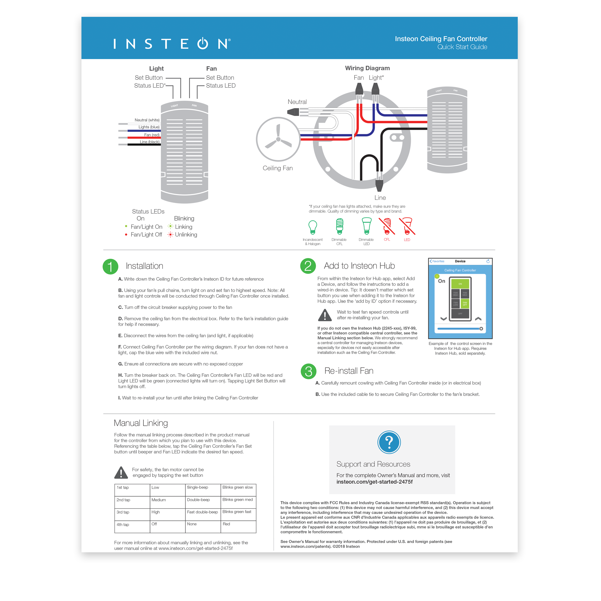
Keypad Button Grouping for Fanlinc Control
After linking a keypad to a Fanlinc (#2475F, 2445-xxx), the buttons will still need some setup so that they respond as intended when activated. Follow the steps below to get your Keypad buttons grouped without software.
Start from the keypad with all LEDs off
Step 1: Tap the A button to turn it ON, then press and hold the set button for 3 seconds.
The A button will begin to flash.
Step 2: Next tap the set button again. (This puts the device into multi-linking mode)
The A button will start rapidly flashing in its multi scene mode.
Step 3: Next press and hold button B for 10 seconds, then button C, and finally Button D.
As you hold them down you will hear a double beep or chirping sound letting you know they have been properly paired.
Step 4: Tap the A button when finished.
Repeat this process for buttons B, C, and D.
The next steps should be done with all the buttons in their OFF state.
Step 5: Tap the A button until it is in the OFF state
Step 6: Press and hold the Set button for 3 seconds
The A button will begin to flash.
Step 7: Tap the button again to put the keypad into multi linking mode.
The A button will start rapidly flashing.
Step 8: Next press and hold button B for 10 seconds, then button C, and finally Button D.
If the Buttons are backlit, simply tap them once so they turn off then press and hold for 10 seconds.
As you hold the buttons down you will hear a double beep, or chirping sound, letting you know they have been properly paired.
Step 9: Tap the A button when finished.
Repeat this process for all other buttons, starting at B, then at C, and finally at D so that all buttons will control all other buttons. This will help to make sure that the Keypad LED reflects the current fan speed.
When finished, tap the buttons to make sure that they are turning On/Off as you press other buttons.
For further instructions, the link below will take you to a video that demonstrates this process.


Identify Insteon Hub IP Address and Port
Use the information in this article to identify the IP Address and Port for Insteon Hub. This information may be required for certain troubleshooting steps but will never be needed for normal operation of your Insteon Hub.
Use Insteon Connect
- Open an internet browser on the same network to which your Insteon Hub is connected and visit connect.insteon.com/getinfo.asp
- All Insteon Hubs on your network that have successfully connected to Insteon Servers within the past 24 hours will appear.
- The IP Address and currently active port will be listed in large text at the top of the block.
- In the example below:
IP Address: http://10.0.1.10
Port Number: 25105

Multiple Insteon Hubs
- If you have more than one Insteon Hub on your network, you can confirm the correct IP Address and Port using the Insteon ID label on the bottom of Insteon Hub.
- Match the Insteon ID on the Insteon ID Label to the Insteon ID presented in the different Insteon Hub blocks.
Automatically Turn Lights On and Off with Sensors

Create Virtual Multi-Way Switches with Director

Amazon Alexa and Supported Insteon Thermostats
Amazon Alexa supports control of several different Insteon Thermostats; you can increase or decrease the temperature and change modes just by asking Alexa. Use the information in this article to identify if you have a compatible Insteon Thermostat.
If you have a supported Thermostat and your Amazon Alexa was configured prior to 18 March 2016, you may need to re-run discovery to identify your Insteon Thermostat. Simply say, "Alexa, discover my devices." Your Amazon Alexa should find your Insteon Thermostats and enable voice control.
Supported Insteon Thermostats
These Insteon Thermostats are compatible with Amazon Alexa and allow full voice control functionality of setting temperature and changing modes.
Insteon Wired Thermostat
- Model 2441TH (Revision 1.1 or later)
Unsupported Insteon Thermostats
These Insteon Thermostats are not explicitly incompatible with Amazon Alexa but are not guaranteed to function as expected.
Insteon Thermostat for Heat Pumps
- Model 2732-242 (Any Revision)
Incompatible Insteon Thermostats
These Insteon Thermostats are incompatible with Amazon Alexa and cannot be controlled.
Insteon Wired Thermostat
- Model 2441TH (Revision 1.0)
Insteon Wireless Thermostat
- Model 2441ZTH
- Model 2441ZTHR
- Model 2732-433
- Model 2732-432
Insteon Venstar Thermostat Adapter
- Model 2441V
- Model 2441VR
Insteon Venstar Integrated Thermostat
- Model 2491T1E
- Model 2491T1ER
- Model 2491T7E
- Model 2491T7ER
Resetting Insteon Hub Time and Location
Deleting your Insteon Account
Communication Types for Insteon Devices
Use this article to determine if your Insteon device can communicate with other Insteon devices via powerline-only, RF-only or powerline and RF (dual-band).
| Powerline | RF | |||
| Dimmer Module | 2456D3 | - | ||
| 2457D2X | - | |||
| 2457D2 | ||||
| On/Off Module | 2456S3 | - | ||
| 2635-222 | ||||
| Outdoor On/Off Module | 2456S3E | - | ||
| 2634-222 | ||||
| LED Bulb | 2672-222 | |||
| LED Bulb for Recessed Lights | 2674-222 | |||
| i3 Paddle | PS01 | |||
| i3 Dial | DS01 | |||
| Dimmer Switch | 2476D | - | ||
| 2477D | ||||
| Dimmer Switch (1000W) | 2476DH | - | ||
| 2477DH | ||||
| Dimmer Switch (2-Wire) | 2474DWH | - | ||
| On/Off Switch | 2476S | - | ||
| 2477S | ||||
| i3 Keypad | KP014 | |||
| Dimmer Keypad (6-Button or 8-Button) |
2486D | - | ||
| 2334-222 | ||||
| On/Off Keypad (6-Button or 8-Button) |
2486S | |||
| 2334-232 | ||||
| Dimmer Outlet | 2474DWH | |||
| i3 Outlet | WR01 | - | ||
| On/Off Outlet (2014) | 2663-222 | |||
| On/Off Outlet (2007) | 2473SWH | - | ||
| Wired Thermostat | 2441TH | - | ||
| Wireless Thermostat | 2441ZTH | - | ||
| Thermostat Adapter | 2441V | - | ||
| Mini Remote (Wireless Switch) |
2444A3 | - | ||
| 2342-242 | - | |||
| Mini Remote (4-Scene) |
2444A2WH4 | - | ||
| 2342-232 | - | |||
| Mini Remote (8-Scene) |
2444A2WH8 | - | ||
| 2342-222 | - | |||
| Wi-Fi Camera | 75790 | - | - | |
| 75790WH | - | - | ||
| HD Wi-Fi Camera | 2864-222 | - | - | |
| 2864-226 | - | - | ||
| Outdoor Wi-Fi Camera | 75791 | - | - | |
| HD Outdoor Wi-Fi Camera | 2864-232 | - | - | |
| Open/Close Sensor | 2421 | - | ||
| 2843-222 | - | |||
| Hidden Door Sensor | 2845-222 | - | ||
| Motion Sensor | 2420M | - | ||
| 2842-222 | - | |||
| Leak Sensor | 2852-222 | - | ||
| Smoke Bridge | 2982-222 | - | ||
| IO Module | 2450 | - | ||
| Ceiling Fan Controller | 2475F | |||
| Dimmer Micro Module | 2442-222 | |||
| On/Off Micro Module | 2443-222 | |||
| Open/Close Micro Module | 2444-222 | |||
| Ballast Dimmer | 2475DA2 | |||
| Dimmer In-Line Module | 2475D | - | ||
| 2475DA1 | ||||
| On/Off In-Line Module | 2475S2 | - | ||
| 2475SDB | ||||
| 220V Load Controller | 2477SA1 | |||
| 2477SA2 | ||||
| Dimmer DIN Rail Module | 2452-222 | |||
| On/Off DIN Rail Module | 2453-222 | |||
| MorningLinc | 2458A1 | - | ||
| Lock Controller | 2862-222 | - | ||
| IRLinc Transmitter | 2411T | - | ||
| IRLinc Receiver | 2411R | - | ||
| SeriaLinc | 2410S | - | ||
| Access Point | 2443 | |||
| Range Extender | 2992-222 | |||
| Energy Display | 2448A2 | - | ||
| iMeter Solo | 2423A1 | - | ||
| SynchroLinc | 2423A5 | - |
Configure Port Forwarding on Apple Routers
Apple Routers use a tool called AirPort Utility for router configuration.
- Launch AirPort Utility from the Utilities folder from within Applications on your Mac. If you are on a PC and using an Apple router, be sure that AirPort Utility has been downloaded and installed from www.apple.com.
- There are two different versions of AirPort Utility.
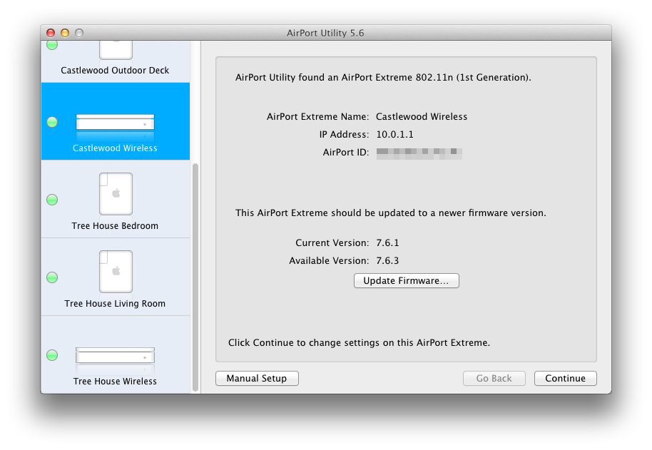
AirPort Utility (5.x)
- Click on your AirPort Express or AirPort Extreme from the left sidebar.
- At the top of the window, click the Internet button.
- lick the DHCP button near the top of the window.
- Click the small “+” button beneath the DHCP Reservation section.
- Enter the following information on the DHCP Reservation Setup Assistant panel.
- Description: Insteon Wi-Fi Camera
If you have more than one Wi-Fi camera, use a name that is unique and descriptive of it's location in your home. - Reserve Address: MAC Address
- Description: Insteon Wi-Fi Camera
- When finished, click Continue.
- Enter the following information on the next page of the DHCP Reservation Setup Assistant panel. You will need to pick an IP Address that is not already in use. We suggest something like 10.0.1.222. Make note of this address as you will need it later. You can find your Wi-Fi camera's MAC Address on the underside of the camera.
- If your camera will be connected with an ethernet cable, enter the MAC Address from the larger label.
- If your camera will be connected with Wi-Fi, enter the MAC Address from the smaller label. This label may also state "Wi-Fi MAC."
- MAC Address: 00:AA:00:AA:00:AA
- IPv4 Address: 10.0.1.222
- When finished, click Done.
- Click the NAT button at the top of the window.
- Click the Configure Port Mappings button.
- Click the small “+” button beneath the Port Mappings section.
- Fill out the fields for your Wi-Fi Camera. The Public and Private TCP Ports should match the port displayed by your Camera. Leave the Service menu and UDP Ports blank. The Private IP Address is the one that you wrote down previously. When finished, click Continue.
- Enter the same description as that used in Step 5 and click Done.
- At the bottom of the configuration panel, click the Update button. Your router will restart. You should also restart your Wi-Fi Camera by disconnecting and reconnecting it to power.
To test your connection, turn off Wi-Fi on your smartphone and attempt to view your camera. If you can control and monitor your camera when not using Wi-Fi, then everything has been successfully configured. If not, something unforeseen may be complicating matters and we suggest that you contact Insteon Support for troubleshooting.

AirPort Utility (6.x)
- Click on your AirPort Express or AirPort Extreme.
- Click on the Edit button on the popup that appears.
- At the top of the panel that drops down, click the Network button.
- Click the small “+” button beneath the DHCP Reservation section.
- Fill out the fields for your Wi-Fi Camera. You will need to pick an IP Address that is not already in use. We suggest something like 10.0.1.222. Make note of this address as you will need it later. You can find your Wi-Fi Camera's MAC Address on the bottom of the camera.
- Description: Insteon Wi-Fi Camera
- If you have more than one Wi-Fi camera, use a name that is unique and descriptive of it's location in your home.
- Reserve Address: MAC Address
- MAC Address: 00:AA:00:AA:00:AA
- IPv4 Address: 10.0.1.222
- If your camera will be connected with an ethernet cable, enter the MAC Address from the larger label.
- If your camera will be connected with Wi-Fi, enter the MAC Address from the smaller label. This label may also state "Wi-Fi MAC."
- If your camera will be connected with an ethernet cable, enter the MAC Address from the larger label.
- When finis hed, click Save.
- Description: Insteon Wi-Fi Camera
- Click the small “+” button beneath the Port Settings section.
- Fill out the fields for your Wi-Fi Camera. The Public and Private TCP Ports should match the port displayed by your Camera. Leave the UDP Ports blank. The Private IP Address is the one that you wrote down in the previous step.
- When finished, click Save.
- At the bottom of the configuration panel, click the Update button. Your router will restart. You should also restart your camera by disconnecting and reconnecting it to power.
To test your connection, turn off Wi-Fi on your smartphone and attempt to view your camera. If you can control and monitor your camera when not using Wi-Fi, then everything has been successfully configured. If not, something unforeseen may be complicating matters and we suggest that you contact Insteon Support for troubleshooting.
Identify your Insteon Hub Version
Locate your device's Insteon ID
All Insteon devices except for WiFi Cameras have an Insteon ID. Use this article to help locate the Insteon ID for your product.
The Insteon ID is usually printed on a small, white rectangular sticker affixed in the locations described below. All Insteon IDs take the form of three hexadecimal pairs (A1.B2.C3).
| Device | Insteon ID Location |
|---|---|
| Dimmer Module | On the back |
| On/Off Module | |
| Outdoor On/Off Module | |
| LED Bulb | On the top of the bulb lens |
| LED Bulb for Recessed Lights | |
| Dimmer Switch | On the metal mounting bracket in one of the four corners |
| Dimmer Switch (1000W) | |
| Dimmer Switch (2-Wire) | |
| On/Off Switch | |
| Dimmer Keypad (6-Button) | |
| Dimmer Keypad (8-Button) | |
| On/Off Keypad (6-Button) | |
| On/Off Keypad (8-Button) | |
| Dimmer Outlet | |
| On/Off Outlet (2007) | |
| On/Off Outlet (2014) | |
| Wired Thermostat | On the inside of the cover as well as near the screw terminals |
| Wireless Thermostat | |
| Thermostat Adapter | On the back |
| Mini Remote (Wireless Switch) | On the back, towards the bottom |
| Mini Remote (4-Scene) | |
| Mini Remote (8-Scene) | |
| WiFi Camera | This device does not have an Insteon ID |
| HD WiFi Camera | |
| Outdoor WiFi camera | |
| HD Outdoor WiFi Camera | |
| Open/Close Sensor | On the circuit board beneath the enclosure cover |
| Hidden Door Sensor | On the circuit board beneath the battery |
| Motion Sensor | On the back, above the battery cover |
| Leak Sensor | On the bottom |
| Smoke Bridge | On the back |
| IO Module | On the back |
| Ceiling Fan Controller | On the bottom |
| Dimmer Micro Module | On the back |
| On/Off Micro Module | |
| Open/Close Micro Module | |
| Ballast Dimmer | On the top |
| Dimmer In-Line Module | On the back |
| On/Off In-Line Module | |
| 220V Load Controller | On the front |
| Dimmer DIN Rail Module | On the back |
| On/Off DIN Rail Module | |
| MorningLinc | On the back |
| IRLinc Transmitter | |
| IRLinc Receiver | |
| SeriaLinc | |
| Range Extender | On the back |
| Energy Display | On the back |
| iMeter Solo | On the back |
| SynchroLinc |