Getting Started


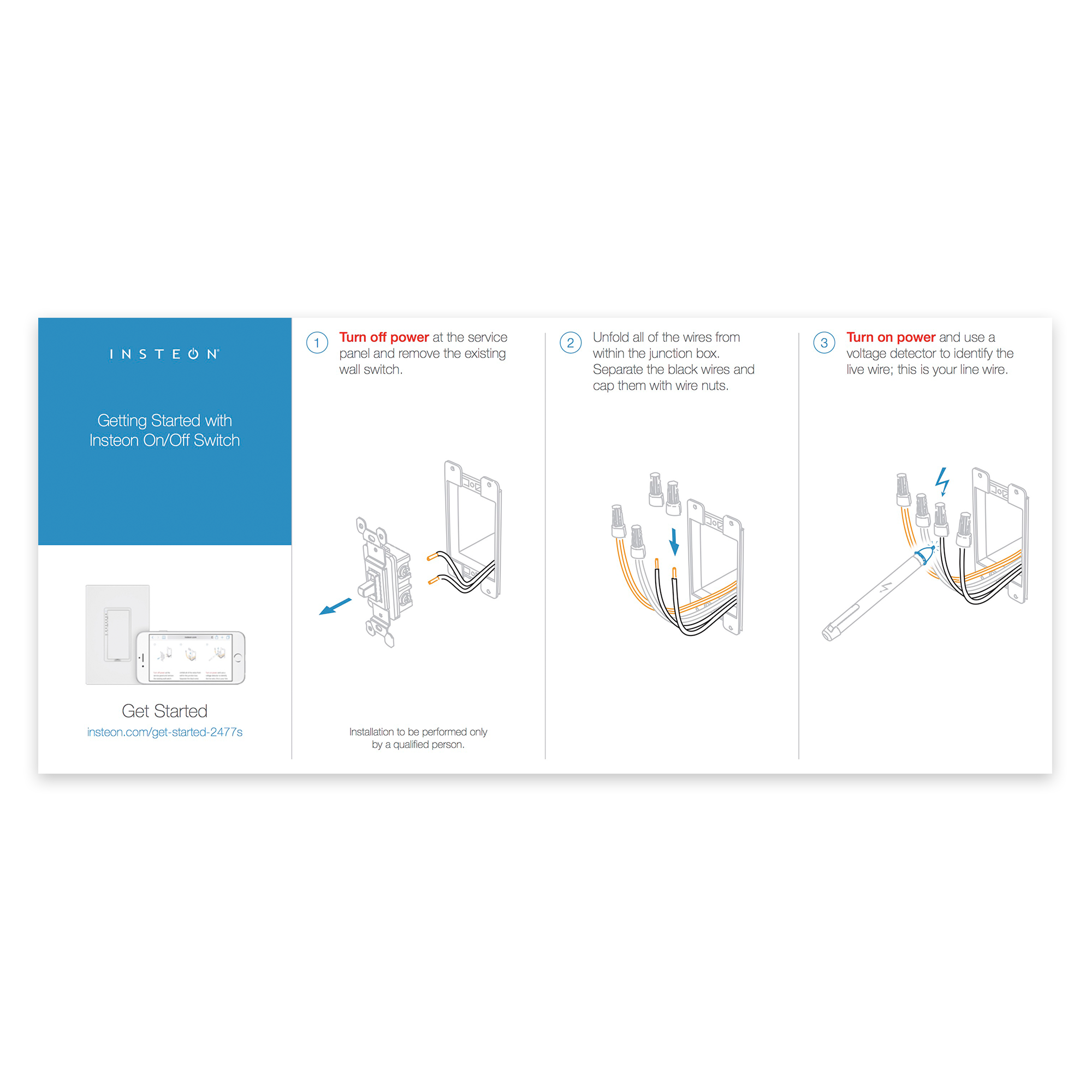
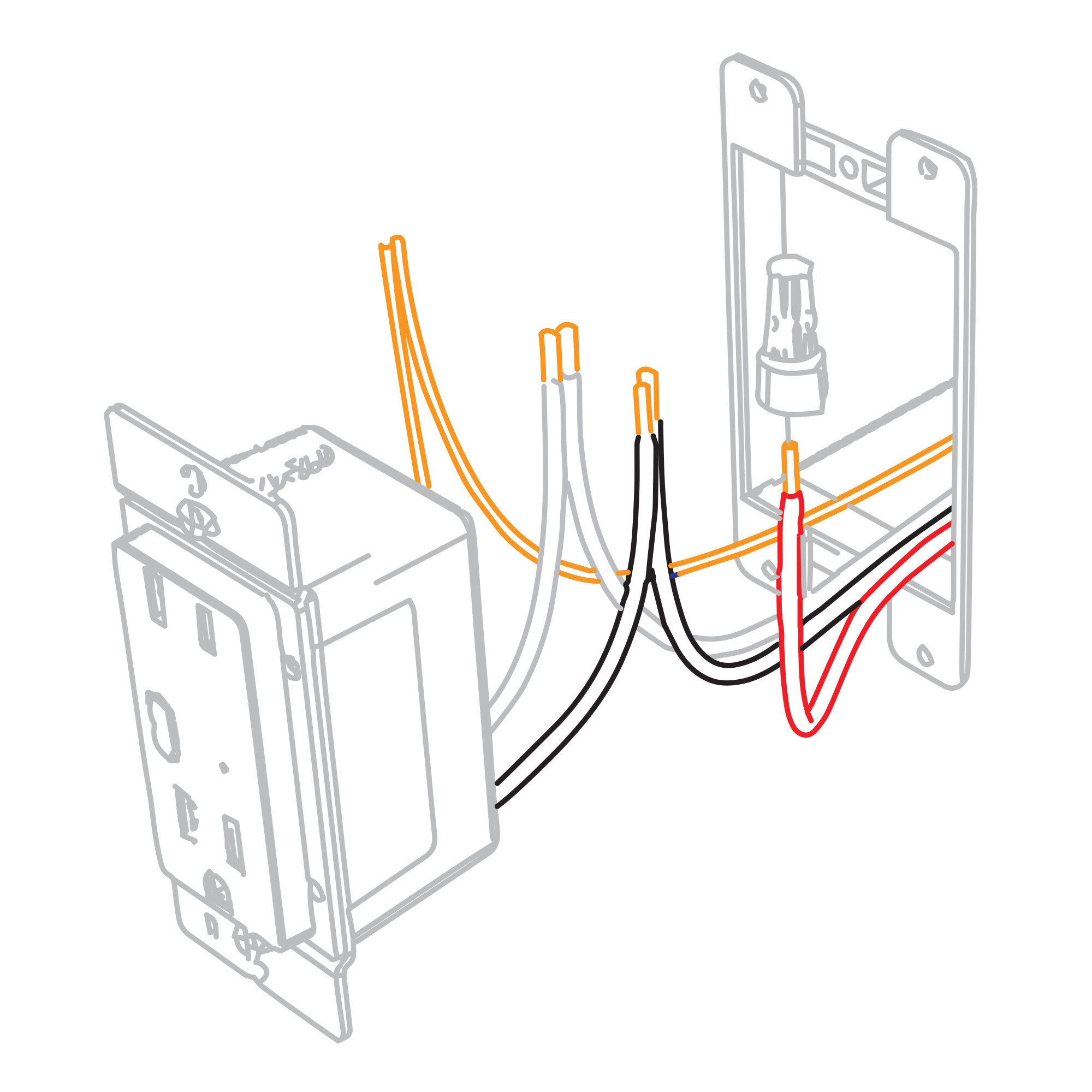
Connect the corresponding wires from the junction box to the Insteon Wall Outlet and cap them with wire nuts.
if your outlet's wires do not match the diagram, consult the additional wiring diagrams available below.


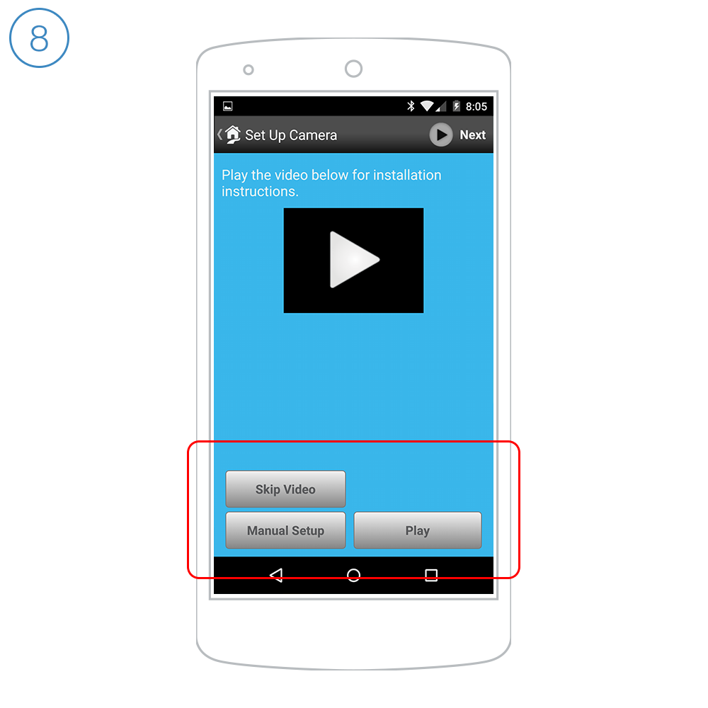
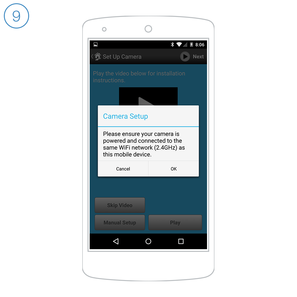
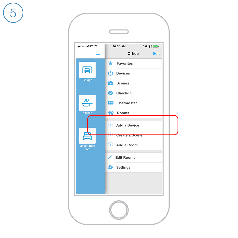
Follow the on-screen instructions in the Insteon app to add Dimmer Outlet.

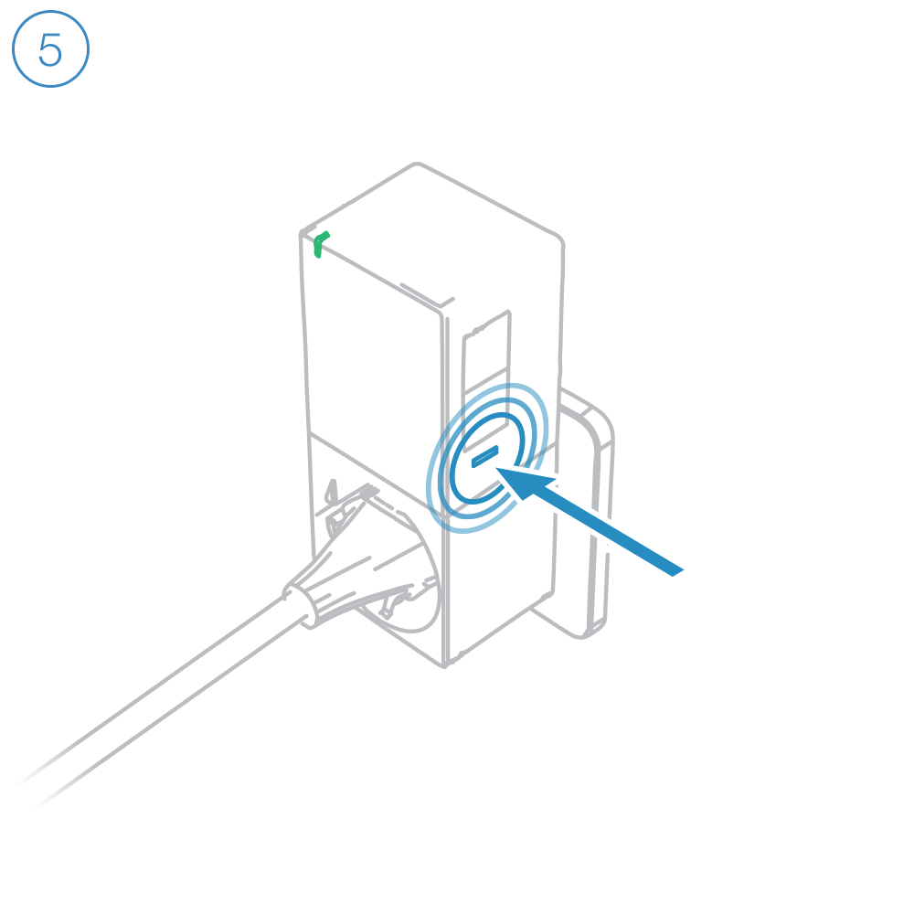
When prompted, press and hold Dimmer Outlet's set button until you hear a double beep.
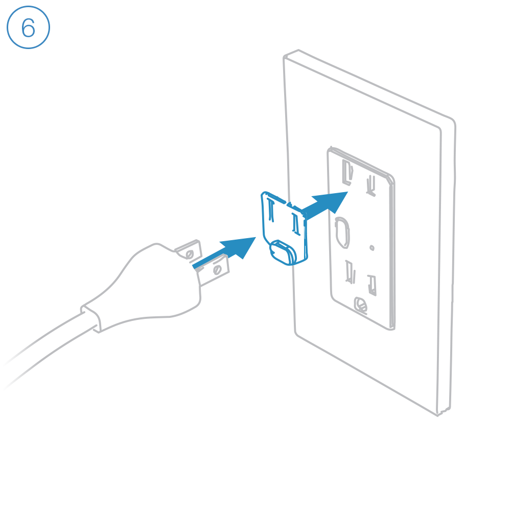
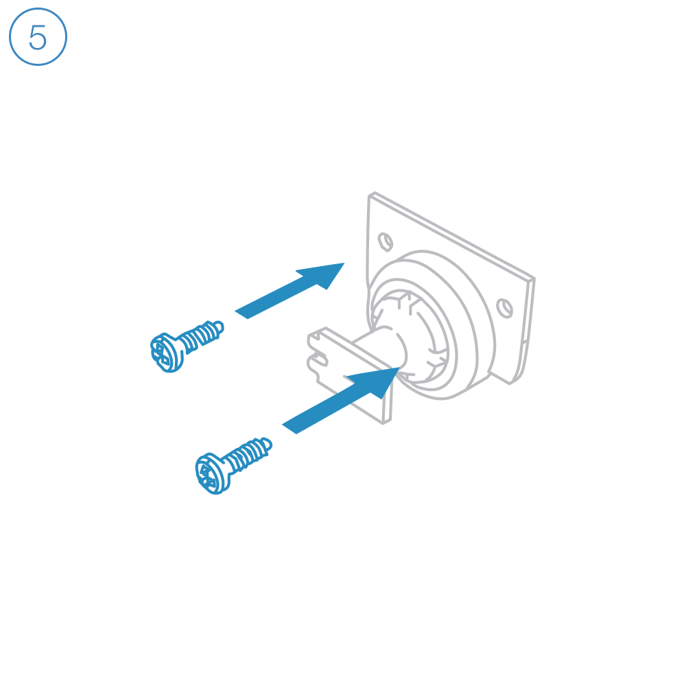
Dimmer Outlet requires that the Outlet Dimmer Key be fitted to any plug connected to the top, dimmable outlet.
Bulb Compatibility

Only connect lamps with dimmable bulbs to Dimmer Outlet's upper outlet.
Guides and Manuals
Quick Start Guides

Owner's Manuals

Wiring Diagrams
End of Run Outlet
Connect the Line, Neutral and Ground wires.

Middle of Run Outlet
Connect the Line, Neutral and Ground wires. If your old outlet connected to ground with a pigtail, you can discard it.

Switched Outlet
Connect the Line, Neutral and Ground wires. Disconnect and cap the switched wire (usually red).
In this configuration, the wall switch that controls this outlet will no longer function. If you would like to preserve control of your outlet from the wall switch, replace the switch with Insteon Wall Switch.
In the junction box that houses the wall switch, replace the standard switch with an Insteon Wall Switch. Connect the Line, Neutral and Ground wires. Cap the switched wire (usually red). Cap the red load wire on the Insteon Switch.
After wiring is complete, link the Insteon Wall Outlet and Wall Switch together.
Turn on both the Insteon Outlet and the Insteon Wall Switch. On Insteon Wall Switch, press and hold the set button until Wall Switch beeps.
On Insteon Wall Outlet, press and hold the set button until Wall Outlet double-beeps.
On Insteon Wall Outlet, press and hold the set button again until Wall Outlet beeps.
On Insteon Wall Switch, press and hold the set button until Wall Switch double-beeps.