Keypad Button Grouping for Fanlinc Control

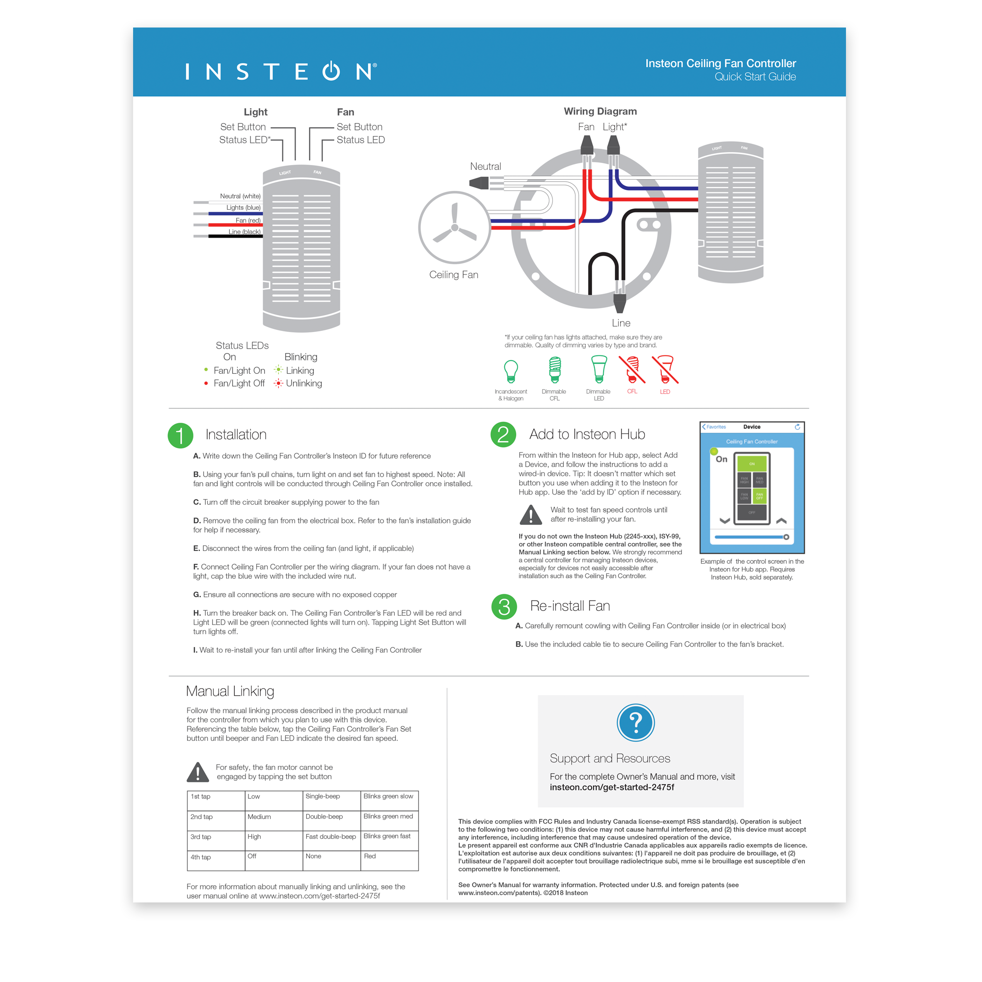
After linking a keypad to a Fanlinc (#2475F, 2445-xxx), the buttons will still need some setup so that they respond as intended when activated. Follow the steps below to get your Keypad buttons grouped without software.

Start from the keypad with all LEDs off

Step 1:  Tap the A button to turn it ON, then press and hold the set button for 3 seconds.

The A button will begin to flash.

Step 2: Next tap the set button again. (This puts the device into multi-linking mode)

The A button will start rapidly flashing in its multi scene mode.

Step 3: Next press and hold button B for 10 seconds, then button C, and finally Button D. 

As you hold them down you will hear a double beep or chirping sound letting you know they have been properly paired.

Step 4: Tap the A button when finished.

Repeat this process for  buttons B, C, and D.

The next steps should be done with all the buttons in their OFF state.  

Step 5: Tap the A button until it is in the OFF state

Step 6: Press and hold the Set button for 3 seconds

The A button will begin to flash.

Step 7: Tap the button again to put the keypad into multi linking mode.

The A button will start rapidly flashing.

 Step 8: Next press and hold button B for 10 seconds, then button C, and finally Button D.  

If the Buttons are backlit, simply tap them once so they turn off then press and hold for 10 seconds.

As you hold the buttons down you will hear a double beep, or chirping sound, letting you know they have been properly paired.

Step 9: Tap the A button when finished.

Repeat this process for all other buttons, starting at B, then at C, and finally at D so that all buttons will control all other buttons.  This will help to make sure that the Keypad LED reflects the current fan speed.

When finished, tap the buttons to make sure that they are turning On/Off as you press other buttons.

For further instructions, the link below will take you to a video that demonstrates this process.

Button Grouping How To Video

How to Wire the Water Shutoff Valve

Follow the steps below on how to properly wire and setup your Insteon Water Shutoff Valve.

Parts required:

2450 - Insteon I/O Linc

70275 - 3/4" Electronic Water Shutoff Valve

70412 - 12V DC Power Supply for Water Shutoff Valve

Wiring Instructions:

Step 1: From the Valve, wire the Green wire to the N/C terminal on the I/O Linc

Step 2: From the Valve, wire the Red wire to the N/O terminal on the I/O Linc.

Step 3: From the power supply***, wire the positive side to the COM terminal on the I/O Linc

***You will need to cut off the barrel of the power supply so you can wire the leads into the IO Linc

Step 4: From the Valve, wire the black wire to the unused wire on the power supply.

After you have finished wiring the shutoff valve to the I/O Linc, plug the I/O Linc into the wall for power. Tap the set button on the side of the I/O Linc. Each press will cause the shutoff valve to close, or open. You can now link the I/O Linc into your Hub app, or manually link it to an Insteon controller, like a water leak sensor.


Control your Insteon Hub from your Android Wear Device using Tasker

If you would like to get more out of your Android Wear Watch, why not use it to control your Insteon home automation devices?  By using the WearTasker App, it is now possible to run any Insteon task created on your Android smartphone (using the Tasker App) from an Android Wear watch.  Using Tasker on your smartphone, build a list of the Insteon tasks you want to have available on your wrist. Once complete, simply tap the clock on your Android Wear watch, scroll down, and start WearTasker.  Then, simply tap an Insteon task and it will execute on your smartphone.  Enjoy convenient Insteon control - from your wrist!


Insteon is unable to offer support for the steps outlined in this article. Please consult this thread on the Insteon Support Forum to share your experiences with other Insteon customers.


Required Devices

  • A compatible Android smartphone (most devices running Android 4.4 or higher will work)

  • The Tasker Android App

  • An Android Wear-compatible device

  • The Wear Tasker Android App

  • An Insteon Hub (2012) or Insteon Hub (2014)


Getting Started

Before starting with Tasker and WearTasker, there are some pieces information you will need to get your devices setup with Insteon. Take a moment to gather the following information.

  • Insteon Hub User Name and Password. These credentials are different from your Insteon Connect account.

  • For Insteon Hub (2012), this information is located on the bottom of the device

  • For Insteon Hub (2014), this information can be found by navigating to Settings > House Settings > Hub User Name and Password

  • IP Address. Either your Hub's local IP address or if you wish for remote control when you are outside of your home's WiFi network, you will need to configure a DDNS setup.

  • Hub port number. The default port number is 25105. If this has been changed, you can find it by navigating to Settings > House > Port.

  • The to-be-controlled device(s) Insteon ID. See Locate your Device's Insteon ID for more information.


Understanding the URL String

Once you get a feel for the fundamentals, coding commands with the Tasker and WearTasker Apps will become easy. Commands are capable of turning devices on and off, brightening and dimming lights, or having lights dim to a preset brightness level. By taking the information collected above and combining it with Insteon Commands and Variables a command string can be created which will be sent to your hub as a post command. 

Here is the URL String template

http://[User Name]:[Password]@[IP Address]:[Port]/3?0262[Insteon ID]0F[Command Type][Command Variable]=I=3

Here is a sample URL with information

http://danny:insteon@10.0.1.5:25105/3?02623256b80f11FF=I=3

Component Function
User Name Insteon Hub User Name
Password Insteon Hub Password
IP Address Local or public IP address for the Insteon Hub. If a DDNS service has been configured, use the DDNS URL instead
Port Insteon Hub port number. By default, the port is 25105
3?0262 Indicates the beginning of a direct Insteon command. This does not change.
Insteon ID Insteon ID for the controlled device. ID should be formatted without periods: aa00bb
0F This does not change
Insteon Command Two digit command from table A1
Command Variable Two digit dimming variable from table A2
=I=3 Indicates the end of the command. This does not change.

Device Command String Examples

This will turn on a device with ID 12.6E.8D to 75% brightness

http://admin:admin@10.0.1.5:25105/3?026212ce8d0f11bf=I=3

This command will slightly dim the same light

http://admin:admin@10.0.1.5:25105/3?026212ce8d0f1300=i=3

Scene Command String Examples

Command strings for scenes are created in a similar fashion; however, instead of using an Insteon ID, the command string will use a Scene ID. A Scene ID can be found within the Insteon for Hub App by going to Settings > Scenes, select the scene and identify the Group number.  Scenes are limited to on and off commands only.

To turn group 1 on, the command would be

http://admin:admin@10.0.1.5:25105/0?111=I=0

To turn group 1 off, the command would be

http://admin:admin@10.0.1.5:25105/0?131=I=0


Adding Commands into Tasker

  • Open Tasker and navigate to Tasks

  • Tap the + button to create a new task and give it a name

  • After the Edit screen appears, tap the + button again and select Net > HTTP Post and enter your command in the server:port field

  • Go back and tap the Play button to test your command

Adding Control to your Android Wear Device

  • Create a new Task by tapping the + button on the task screen and give it a name

  • On the Edit Task screen, tap + and select Plugin > Wear Tasker

  • Tap the Edit button to configure the task

Configure a Location Profile for quick access to lighting commands

  • Every time your phone connects to a specified WiFi network, your watch will display the desired controls.

  • Go to Profiles and tap the + button

  • Select State > Net > WiFi Connected and then browse for your home's WiFi Network SSID

  • Tap Back and select a Task

  • Select the Task you created for Wear Tasker


General Insteon Control

Insteon Command Function
11 On - Can Be used with Variable to set default brightness level
12 Fast On - Will go immediately to full brightness - No ramp rate
13 Off - Can Be used with Variable to set default brightness level
14 Fast Off - Will go immediately off - No ramp rate
15 Brighten - Incrementally increase brightness of a dimmable device
16 Dim - Incrementally decrease brightness of a dimmable device
 

Brightness

Insteon Command Function
0 0%
19 10%
40 25%
7F 50%
BF 75%
E6 90%
FF 100%
 

Thermostat Control

For the heat and cool set point command strings, ** denotes the desired set point. This command example will switch a Thermostat to Heat:

http://admin:admin@10.0.1.5:25105/3?02623093181F6B040000000000000000000000000091=I=3

Insteon Command Function
1F6B040000000000000000000000000091 Heat On
1F6B050000000000000000000000000090 Cool On
1F6B06000000000000000000000000008F Auto On
1F6B07000000000000000000000000008E Fan On
1F6B08000000000000000000000000008D Fan Off
1F6B09000000000000000000000000008C All Off
1F6C6400000000000000000000000000** Cool Set Point
1F6D6400000000000000000000000000** Heat Set Point

Useful Resources

Probably the most useful resource for generating Insteon Direct Commands, this will allow you to generate the commands automatically for the most useful functions, such as setting brightness levels or changing your thermostat’s temperature.

An excellent rundown and explanation as to just how these direct commands work


"Welcome Home" Lights


Have you ever pulled into the garage and walked into your house with more things to carry than you could handle? After a trip to Costco or the grocery store, it is always a test of how many things we can fit into our hands to make fewer trips between the car and the house. When this happens it can be hard to find a free hand to hit the switch. With Insteon lighting and an Insteon Garage Door and Status Kit you can have the lights turn on automatically for you when you open your garage door so that you don’t spill your things on your way into the house.

For this tip we will use HouseLinc to set up an Event that will turn on lights only after dark when the garage door is opened.  To accomplish this, you will need an Insteon Garage Door and Status Kit, Insteon light switches (or plug-in modules), and HouseLinc.

To begin, you will want to click on the ‘Events’ tab towards the top right hand section of the HouseLinc window. Click the button titled ‘Add Event’ and you can begin programming this welcome home event. You will want to drag your Garage Door IOLinc into the ‘Trigger(s)’ section of this new Event. You will also want to edit the trigger to read ‘Sensor Opened’. This will trigger the Event whenever the magnetic contacts (from your Garage Door and Status Kit) are separated from each other. Next you will want to alter the Event to only operate when it’s Dark outside. Drag the Clock icon into the ‘Condition(s)’ section of the Event and edit this condition to read ‘If it’s Dark outside’. Finally, you will drag your lights from ‘Devices’ on the left hand side of the HouseLinc into the ‘Action(s)’ field of the Event and edit the level appropriately.

If you really want to create a welcoming mood, you can also create a Scene with different lighting levels and drag that into the ‘Action(s)’ section of this event.

Once the settings have been added to the Event, Click OK to save the Event into HouseLinc and enjoy. Now, when you come home at night and you have your hands full your lights will welcome you home.